Latest News >>>   Admissions Open ||   Virtual Student Development Programs >>>> | Basic Electronics |   | Robotics Design |   | Arduino Prototyping |    Skill Development Programmes (NULM)  >> Automotive Service Technician (Level-4)  |  | Sales Executive (VAS) | 
Showing posts with label Electrical. Show all posts

Hydroelectric Power Plant


Hydroelectric (hydel) power plants convert the energy stored in a water into electrical energy by the use of water turbines coupled with generators. The water from a height (water head) is allowed to fall on the blades of a turbine through long pipes or tunnels called penstocks. This causes the turbine blades to rotate which in turn rotates the rotor of an alternator.
A dam is constructed to make a storage reservoir, from where a high pressure tunnel is taken off to the valve house. The penstocks are large pipes, which carry huge quantity of water from valve houses to the power house. A surge tank is situated just beside the valve house. In case due to reduction of load on the turbines the inlet valves to the turbines are suddenly closed, water hammer due to very high pressure is created which may damage the penstocks. Surge tank absorbs water hammer by increase the water level and it. In case of heavy load, it will lower its water level and will increase the water supply to the turbine. The common type of turbine (prime mover) used is Pelton wheel.

ADVANTAGES 
  •    Once a dam is constructed electricity can be produced at a constant rate
  • .   The lake’s water can be used for irrigation purpose
  • .    No need of fuel, because if it operation by using water
  • .    They don’t pollute the atmosphere
  •       Less working and maintenance cost
  •    Construction is simple


DISADVANTAGES
  •  Dams are extremely expensive to build and must be built to a very high   standard.
  • The flooding of large of land means that the natural environment is destroyed.


SELECTION OF SITE 

The following points should be taken into account while selecting the site for hydroelectric station.
1.    Availability of water: Hydel plants should be built at a place [eg: river, canal] where adequate water is available at a good head.
2.  Storage of water: it is necessary to store water by constructing a dam in order to ensure the generation of power throughout the year.
3.    Cost and type of land: The land for the construction of the planet should be available at a reasonable price. Further the bearing capacity of the site should be adequate to withstand the weight of heavy equipments which are to be installed.
4.  Transportation facilities: The site should be accessible by rail and road so that necessary equipment and machinery could be easily transported.

Basic Electrical Terms and Definitions

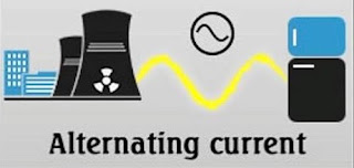
Alternating Current (AC) — An electric current that reverses its direction many times a second at regular intervals.                                                                                 
        
Ammeter — An instrument for measuring the flow of electrical current in amperes. Ammeters are always connected in series with the circuit to be tested.
Ammeter
Ampacity — The maximum amount of electric current a conductor or device can carry before sustaining immediate or progressive deterioration.
Ampere-Hour (Ah) — A unit of measure for battery capacity. It is obtained by multiplying the current (in amperes) by the time (in hours) during which current flows. For example, a battery which provides 5 amperes for 20 hours is said to deliver 100 ampere - hours.
Ampere (A) — A unit of measure for the intensity of an electric current flowing in a circuit. One ampere is equal to a current flow of one coulomb per second.
Apparent Power — Measured in volt-ampers (VA). Apparent power is the product of the rms voltage and the rms current.
Armature — The movable part of a generator or motor. It is made up of conductors which rotate through a magnetic field to provide voltage or force by electromagnetic induction. The pivoted points in generator regulators are also called armatures.
Capacitance — The ability of a body to store an electrical charge. Measured in farads as the ratio of the electric charge of the object (Q, measured in coulombs) to the voltage across the object (V, measured in volts).
Capacitor — A device used to store an electric charge, consisting of one or more pairs of conductors separated by an insulator. Commonly used for filtering out voltage spikes.
Circuit — A closed path in which electrons from a voltage or current source flow. Circuits can be in series, parallel, or in any combination of the two.
Circuit Breaker — An automatic device for stopping the flow of current in an electric circuit. To restore service, the circuit breaker must be reset (closed) after correcting the cause of the overload or failure. Circuit breakers are used in conjunction with protective relays to protect circuits from faults.
Circuit Breaker
Conductor — Any material where electric current can flow freely. Conductive materials, such as metals, have a relatively low resistance. Copper and aluminum wire are the most common conductors.
Corona — A corona discharge is an electrical discharge brought on by the ionization of a fluid such as air surrounding a conductor that is electrically charged. Spontaneous corona discharges occur naturally in high-voltage systems unless care is taken to limit the electric field strength.
Current (I) — The flow of an electric charge through a conductor. An electric current can be compared to the flow of water in a pipe. Measured in amperes.

Current
Cycle — The change in an alternating electrical sine wave from zero to a positive peak to zero to a negative peak and back to zero. See Frequency.
Demand — The average value of power or related quantity over a specified period of time.
Dielectric constant — A quantity measuring the ability of a substance to store electrical energy in an electric field.
Dielectric strength — The maximum electric field that a pure material can withstand under ideal conditions without breaking down (i.e., without experiencing failure of its insulating properties).
Diode — A semiconductor device with two terminals, typically allowing the flow of current in one direction only. Diodes allow current to flow when the anode is positive in relation to the cathode.
Diode
Direct Current (DC) — An electric current that flows in only one direction.
Electrolyte — Any substance which, in solution, is dissociated into ions and is thus made capable of conducting an electrical current. The sulfuric acid - water solution in a storage battery is an electrolyte.
Electromotive Force — (EMF) A difference in potential that tends to give rise to an electric current. Measured in volts.
Electron — A tiny particle which rotates around the nucleus of an atom. It has a negative charge of electricity.
Electron theory — The theory which explains the nature of electricity and the exchange of "free" electrons between atoms of a conductor. It is also used as one theory to explain direction of current flow in a circuit.
Farad — A unit of measure for capacitance. One farad is equal to one coulomb per volt.
Ferroresonance — (nonlinear resonance) a type of resonance in electric circuits which occurs when a circuit containing a nonlinear inductance is fed from a source that has series capacitance, and the circuit is subjected to a disturbance such as opening of a switch. It can cause overvoltages and overcurrents in an electrical power system and can pose a risk to transmission and distribution equipment and to operational personnel.
Frequency — The number of cycles per second. Measured in Hertz. If a current completes one cycle per second, then the frequency is 1 Hz; 60 cycles per second equals 60 Hz.
Fuse — A circuit interrupting device consisting of a strip of wire that melts and breaks an electric circuit if the current exceeds a safe level. To restore service, the fuse must be replaced using a similar fuse with the same size and rating after correcting the cause of failure.
Generator — A device which converts mechanical energy into electrical energy.
Ground — The reference point in an electrical circuit from which voltages are measured, a common return path for electric current, or a direct physical connection to the Earth.
Ground Fault Circuit Interrupters (GFCI) — A device intended for the protection of personnel that functions to de-energize a circuit or portion thereof within an established period of time when a current to ground exceeds some predetermined value that is less than that required to operate the overcurrent protective device of the supply circuit.
Henry — A unit of measure for inductance. If the rate of change of current in a circuit is one ampere per second and the resulting electromotive force is one volt, then the inductance of the circuit is one henry.
Hertz — A unit of measure for frequency. Replacing the earlier term of cycle per second (cps).
Impedance — The measure of the opposition that a circuit presents to a current when a voltage is applied. Impedance extends the concept of resistance to AC circuits, and possesses both magnitude and phase, unlike resistance, which has only magnitude.
Inductance — The property of a conductor by which a change in current flowing through it induces (creates) a voltage (electromotive force) in both the conductor itself (self-inductance) and in any nearby conductors (mutual inductance). Measured in henry (H).
Inductor — A coil of wire wrapped around an iron core. The inductance is directly proportional to the number of turns in the coil. 
Insulator — Any material where electric current does not flow freely. Insulative materials, such as glass, rubber, air, and many plastics have a relatively high resistance. Insulators protect equipment and life from electric shock.
Inverter — An apparatus that converts direct current into alternating current.
Kilowatt-hour (kWh) — The product of power in kW and time in hours. Equal to 1000 Watt-hours. For example, if a 100W light bulb is used for 4 hours, 0.4kWhs of energy will be used (100W x 1kW / 1000 Watts x 4 hours). Electrical energy is sold in units of kWh.
Kilowatt-hour Meter — A device used to measure electrical energy use.
Kilowatt (kW) — Equal to 1000 watts.
Load — Anything which consumes electrical energy, such as lights, transformers, heaters and electric motors.
Load Rejection — The condition in which there is a sudden load loss in the system which causes the generating equipment to be over-frequency. A load rejection test confirms that the system can withstand a sudden loss of load and return to normal operating conditions using its governor. Load banks are normally used for these tests as part of the commissioning process for electrical power systems.
Mutual Induction — Occurs when changing current in one coil induces voltage in a second coil.
Ohm — (Ω) A unit of measure of resistance. One ohm is equivilant to the resistance in a circuit transmitting a current of one ampere when subjected to a potential difference of one volt.
Ohm's Law — The mathematical equation that explains the relationship between current, voltage, and resistance (V=IR).
Ohmmeter — An instrument for measuring the resistance in ohms of an electrical circuit.
Ohm Meter
Open Circuit — An open or open circuit occurs when a circuit is broken, such as by a broken wire or open switch, interrupting the flow of current through the circuit. It is analogous to a closed valve in a water system.
Parallel Circuit — A circuit in which there are multiple paths for electricity to flow. Each load connected in a separate path receives the full circuit voltage, and the total circuit current is equal to the sum of the individual branch currents.
Parallel Circuit
Piezoelectricity — Electric polarization in a substance (especially certain crystals) resulting from the application of mechanical stress (pressure).
Polarity — A collective term applied to the positive (+) and negative ( - ) ends of a magnet or electrical mechanism such as a coil or battery.
Power — The rate at which electrical energy is transferred by an electric circuit. Measured in Watts.
Power Factor — The ratio of the actual electrical power dissipated by an AC circuit to the product of the r.m.s. values of current and voltage. The difference between the two is caused by reactance in the circuit and represents power that does no useful work.
Protective Relay — A relay device designed to trip a circuit breaker when a fault is detected.
Reactive Power — The portion of electricity that establishes and sustains the electric and magnetic fields of AC equipment. Exists in an AC circuit when the current and voltage are not in phase. Measured in VARS.
Rectifier — An electrical device that converts an alternating current into a direct one by allowing a current to flow through it in one direction only.
Half wave Rectifier
Relay — An electrical coil switch that uses a small current to control a much larger current.
Reluctance — The resistance that a magnetic circuit offers to lines of force in a magnetic field.
Resistance — The opposition to the passage of an electric current. Electrical resistance can be compared to the friction experienced by water when flowing through a pipe. Measured in ohms.
Resistor — A device usually made of wire or carbon which presents a resistance to current flow.
Resistor
Rotor — The rotating part of an electrical machine such as a generator, motor, or alternator.
Self Induction — Voltage which occurs in a coil when there is a change of current.
Semiconductor — A solid substance that has a conductivity between that of an insulator and that of most metals, either due to the addition of an impurity or because of temperature effects. Devices made of semiconductors, notably silicon, are essential components of most electronic circuits.
Series-Parallel Circuit — A circuit in which some of the circuit components are connected in series and others are connected in parallel.
Series Circuit — A circuit in which there is only one path for electricity to flow. All of the current in the circuit must flow through all of the loads.
Service — The conductors and equipment used to deliver energy from the electrical supply system to the system being served.
Short Circuit — When one part of an electric circuit comes in contact with another part of the same circuit, diverting the flow of current from its desired path.
Solid State Circuit — Electronic (integrated) circuits which utilize semiconductor devices such as transistors, diodes and silicon controlled rectifiers.
Transistor — A semiconductor device with three connections, capable of amplification in addition to rectification.
True Power — Measured in Watts. The power manifested in tangible form such as electromagnetic radiation, acoustic waves, or mechanical phenomena. In a direct current (DC) circuit, or in an alternating current (AC) circuit whose impedance is a pure resistance, the voltage and current are in phase.
VARS — A unit of measure of reactive power. Vars may be considered as either the imaginary part of apparent power, or the power flowing into a reactive load, where voltage and current are specified in volts and amperes.
Variable Resistor — A resistor that can beadjusted to different ranges of value.
Volt-Ampere (VA) — A unit of measure of apparent power. It is the product of the rms voltage and the rms current.
Volt (V) — A unit measure of voltage. One volt is equal to the difference of potential that would drive one ampere of current against one ohm resistance.
Voltage — An electromotive force or "pressure" that causes electrons to flow and can be compared to water pressure which causes water to flow in a pipe. Measured in volts.
Voltage
Voltmeter — An instrument for measuring the force in volts of an electrical current. This is the difference of potential (voltage) between different points in an electrical circuit. Voltmeters have a high internal resistance are connected across (parallel to) the points where voltage is to be measured.
Voltmeter
Watt-hour (Wh) — A unit of electrical energy equivalent to a power consumption of one watt for one hour.
Watt (W) — A unit of electrical power. One watt is equivalent to one joule per second, corresponding to the power in an electric circuit in which the potential difference is one volt and the current one ampere.
Wattmeter — The wattmeter is an instrument for measuring the electric power (or the supply rate of electrical energy) in watts of any given circuit.
Wattmeter
Waveform — A graphical representation ofelectrical cycles which shows the amount of variation in amplitude over some period of time.

Generation and Distribution of Electric Power


The process of generating electricity follows a sequence that takes charge from the ground and works on it to produce energy. This energy is expressed in terms of voltage. The energy is transported through a system of distribution making use of energy and dumping the charge that has been spent back to the earth again. The Earth is used as a reservoir for charge and at the same time the reference potential for the transfer process of energy. In simple terms, the Earth is basically the charge reservoir from where electric charge is drawn and to which the charge is taken back after the energy has been put to use. However, we cannot rely on the “ground” connection to this same earth to be adequate as the path through which the charge goes back to the Earth. Particularly, a mere connection to a rod for grounding is not adequately low resistance pathway to guarantee protection from shock through a quick carriage of the charge to the Earth in the event that a short circuit is realized on the ground. For the safety of electric generation and distribution, the ground wire used should be bonded back to the supply transformer that is neutral to compel the tripping of the breaker in a ground fault condition.

The power station is the industrial facility that is mainly used to generate electric power. The main center for almost all stations of power is the generator. A generator is a rotating machine that transforms mechanical energy into electrical form through the creation of a relative motion in between a field of magnetism and a conductor (Von Meier 10-84). The source of energy is harnessed to turn the generator. However, there exist great differences. It relies mainly on the fuels that are readily available and on the kind of technology that can be accessed.

Electricity Generation


Generation of electricity is achievable through various methods. There are about seven significant methods through which other forms of energy can be transformed into electrical energy. The generated electricity from whatever form can be connected with the main grid for transmission. One of the ways through which electricity can be generated is through a process of physical separation and distribution of charge. This is what is commonly known as static electricity. Lightning and triboelectric effect are good examples in this category. Basically energy is the capacity of doing work. Energy around the universe exists in different forms, like thermal energy, mechanical energy, solar energy and electrical energy among others. Electric power happens to be the only form of energy, which is indeed easy to generate and distribute. Its distribution, use and control are also very easy.

Electromagnetic induction is also another way through which electricity can be generated. In this process, an electrical generator, alternator or dynamo converts the kinetic form of energy which is basically energy in motion into the desired electricity form. This is the commonly used nature of generating electricity and it is founded on Faraday’s law. A good experimentation of this process can be realized through merely rotating a piece of magnet inside a closed loop of material that can conduct electricity like Copper wire.

Electrochemistry also forms part of the different ways of the electricity generation effort. It involves the direct conversion of chemical energy from its form into electricity. This is seen in a fuel cell, nerve impulse or in a battery. Photoelectric effect, on the other hand, involves the conversion of light into electricity as seen in solar cells. Thermoelectric effect as a form of electricity generation is the direct transformation of the differences in temperature to electricity as in thermopiles, thermocouples and thermionic converters. Piezoelectric effect is also another electricity generating process. Energy in mechanical form from an electrically anisotropic crystals or molecules can be effectively converted to electricity. Last but not the least, nuclear transformation in generating electricity involves the formation and acceleration of particles that are charged like in alpha particle emission and betavoltaics.

In most case, commercial generation of electricity is made possible through electromagnetic induction where energy in mechanical form forces an electrical generator to revolve. There are various ways through which mechanical energy can be developed. This includes hydro means, tidal power, wind energy and heat engines. The direct transformation of nuclear potential form of energy to electricity through beta decay is utilized only on a very small scale. In a complete nuclear power plant, the nuclear reaction heat is utilized to run a heat engine. This is used to run a generator which then transforms the energy from a mechanical form into electricity through a process of magnetic induction.

Many of the electric generation types are run through heat engines. The burning of fossil fuels provides most of the heat needed by the engines with a very big portion from nuclear fission and some other kind from sources that are renewable. The contemporary steam turbine that was invented in 1884 by Sir Charles Parsons, presently generates almost 80% of the total power of electricity around the world using different sources of heat.

Turbines are mechanical components that are very useful in the electricity generation process. All turbines are moved by a fluid that acts as an intermediate carrier of energy. Most of the heat engines are these kinds of turbines. Other turbines can be run by falling power in hydro-electric power generation or even driven by wind. Electric power is generated through the prime movers like the steam turbines, hydraulic turbines, and diesel engines. A lot of electric power is generated and formed using the prime movers in a layout or site which is commonly known as a power plant. In a power plant, all the equipments, components and machineries needed for the electric power generation process are located.

Electric power is principally connected to mechanical energy and work and the electrical energy as well. Thus, power can be described as the rate at which energy flows. Therefore, a power plant is a basic unit that has been constructed to produce and deliver this flow of energy from a mechanical form to electrical energy. In a common application, an assemblage of machine components that produce and enhance the flow of electrical and mechanical energy is what is called a power plant. Therefore, an internal combustion engine is actually a power plant. Other power plants include a water wheel and the list includes many others. All the same, the term power plant conventionally refers to the assemblage of machine components, permanently installed on some chosen location that receives energy in raw form which is mainly a substance that can be worked on in such a manner that produces electrical energy for distribution from the set of arrangement in the power plant (Von Meier 10-84).

All power plants share a lot of remembrances. The only thing that differs is the medium and form of energy that is used to generate electricity. For example, a steam power plant generates steam through the water heated by nuclear fission. The combustion of fossil fuels like natural gas, coal or petroleum produces gases that drive turbines directly. However, there can be a gas turbine plant with a combined cycle where the gas turbine is driven by both the natural gas and steam. They generate power through the combustion of natural gas in this gas turbine and utilize residual heat as a means of generating extra electricity from the steam.

In a hydroelectric power plant, a large amount of electric power is produced through the turbines driven by falling water. The blades of the turbine are acted upon by falling water from tidal forces or through hydroelectric dams. Turbines can also be driven by wind to generate electricity. Naturally occurring, wind can be useful enough to drive turbines.

After electricity has been generated, the next process involves the transportation of generated power. Electricity transmission involves the transfer of the generated electric power from the power plants to reach the consumers by way of different types of lines of transmission and transformers (Willis 34-56). The distribution of electrical power is the last stage in the supply of electric power to end users.

Types of Electric Power Transmissions


Electric power can either be transmitted through overhead power lines or through underground means. An overhead line of power is an electric power line of transmission that is usually suspended through poles or towers. These overhead lines of power are regarded as the cheapest transmission methods for huge quantities of electricity because air provides the insulation. One of the major goals of utilizing overhead line design is to maintain a good clearance between the conductors that have been energized and the ground in an effort of preventing hazardous contact with the line. The overhead transmission lines of electric power are categorized and based on their voltages as low-voltage, medium voltage, high voltage, extra high voltage and ultra high voltage (more than 800 kV). The low-voltage line is normally less than 1 kV and is basically used to connect residential and commercial users. The medium-voltage, on the other hand, ranges between 1 kV to 33 kV for distribution both in rural and urban centers. The high voltage forms ranges from 33 kV to 230 kV utilized for both sub-transmission together with transmission of large quantities of electricity (Willis 34-56).

On the other hand, there are underground power cables that can be used to transmit electricity. The underground transmission is becoming widely accepted as a very viable option to the overhead power lines of transmission. This has mainly been occasioned by fast-track projects of transmissions, the load in urban areas and the quickly advancing technologies as well as the deflating costs of cable systems of high voltage. Underground transmission provides the advantages of less subject to ruin from bad weather, largely reduced emissions of electromagnetic fields into the neighboring environment, narrow surrounding strip needed for underground cables and the fact that there is no hazard to wildlife and low flying aircraft.

Electric Power Distribution Systems


A network system of distribution carries the electric power from the system of transmission and takes it to the consumers. In general, the network would comprise a medium-voltage which is usually below 50kV lines of power, substations and transformers mounted on poles, low-voltage (about 1kV) transportation wiring and in some cases meters. All these components are useful in the electric power distribution process.

The electric energy that has been obtained in the process of generating electricity should be distributed to the end users through electric conductors. However, the process of transmission is often faced with a lot of challenges as because of resistive losses of power. A major party of the plan of transmission takes into account the use of transformers. Transformers multiply the voltage to thousands of volts as a way of minimizing the loss that is occasioned by the heat in the wires of transmission (Willis 34-56).

Power can be distributed in three-phase form where a conductor is in 120 degrees in phase and away from the other conductors. When each section of the huge insulators can withstand a 10,000 volts working voltage, these conductors could be operating at a value of 150,000 volts.

The transmission lines are mainly constructed between substations of transmission situated at the electric power generating stations (Von Meier 10-84). The lines of transmission could be supported overhead on huge towers or they could be installed underground. They are normally operated at very high voltages. They send out enormous amounts of electricity and extend over relatively large distances.

The moment electricity leaves a generating station; the transmission substation situated there is used to step up the voltages. The stepped up value ranges between 138kV and 765kV. Within the area of operation, the substations of transmissions cut down the voltage that has been transmitted to about 34.5 kV and 138 kV. This electric power is then transported through the lines to the systems of distribution situated in the local service field (Willis 34-56). The main hazards realized during the process of transmission are mainly electrical. The failure to maintain enough approach distances or making use of suitable equipment for protection like sleeves and rubber gloves can amount to injuries or even death in the event of an accident.

The system of distribution links to the system of transmission to the equipment of the consumer. The substation distribution cuts down the electrical voltage that has been transmitted to lesser values about 2400 to 19920 volts. A transformer in the distribution channel again cuts down the voltage. The hazards that are related to the work of distribution are also in electrical form. All the same, there is an extra hazard of working in places that are enclosed. Working in vaults and manholes can be dangerous in the distribution process. This is more in particular when handling an underground system of distribution.

The contemporary system of distribution starts as the primary circuit leaves the elementary sub-station and ends as the secondary service reaches the meter socket of the consumer. The circuits of distribution serve very many consumers. The voltage utilized is suitable for the shorter distance and ranges between 2300 volts and 35000 volts. This depends on the distance, utility standard practice and the load that is to be supplied. The circuits of distribution are fed from the transformer that situated in an electrical sub-station. In this electrical substation, the voltage is reduced by the transformer from high values to make it possible for the process of transmission (Von Meier 10-84).

The conductors that are used in distribution could be carried over on overhead lines of poles or may be buried underground in areas that are densely-populated. Distribution in the suburban and urban areas is done with 3-phase systems to serve industrial, residential and commercial loads. On the other hand, rural power distribution is done in single-phase, for instance, whereby it is not economically feasible to install three-phase electric power for comparatively small and few customers.

All the same, huge customers can be supplied directly from the voltages of distribution. Many of the utility customers are linked to a transformer. This reduces the voltage of distribution to a comparatively low voltage that is utilized through lighting and interior systems of wiring. The transformer could be mounted on a pole or mounted in a safe ground. In the rural centers, a pole-mounted transformer could be used to serve a single customer, although in areas that are well built-up, a number of customers can be connected. In the densely populated city regions, a secondary network system could be created with many transformers supplying a common bus at the usage voltage. All customers have a service drop or electrical service connection and a meter that is used for the purposes of billing. Some small loads like yard lights could be too small to meter and, thus, are charged only on a rate of a given month (Willis 34-56).

A ground connection to the local earth is usually provided for the system of the consumer and also for the equipment that is possessed by the utility. The main objective of linking the system of the consumer to the ground is to limit the amount of voltage that could develop if conductors of high voltage fall on the conductors of lower voltage. They could also be useful in the event of a failure taking place within the transformer in the distribution line. Suppose all conductive objects are together bonded to a similar system of earth grounding, electric shock risk is completely minimized (Willis 34-56). All the same, many connections between the customer ground and the utility ground can result in problems of stray voltage, swimming pools, piping of customers and the development of objectionable voltages in other equipment. These issues could be hard to resolve because they usually originate from places rather than from the premises of the consumers.

The distribution and transmission substations are installations where the phase, voltage and other electrical energy characteristics are altered as part of the final process of distribution. Electrocutions characterize the primary safety hazards in the substations. Such kinds of accidents are normally caused by the failure to apply the correct distances of approach and failure to use the proper personal protective equipment.

The process of generating, transmitting and distributing electric power is a very sequential process that is controlled and managed in a series of steps. The generation of electric power is a process that involves the conversion of power from different forms into electricity. As discussed in this essay, power can be harnessed from water, wind, natural gas and electrochemistry among other sources. However, despite the different sources, the conversion of other forms of energy into electricity follows a standardized procedure. Most of the commonly used form of electrical energy is a conversion from mechanical energy in different mediums and locations.

The generation of electricity takes place in a power plant. This is basically an assemblage of machine components that harnesses a particular source of energy and converts the energy into electricity through electromagnetic induction. The series of components in the power station include turbines and generators that aid in the electricity production process. Once the electricity has been generated, it is now ready for transmission and distribution.

The transmission and distribution of electricity happens to be a very important process. There are a lot of challenges involved in the distribution of electricity to customers. The heat of the conductors can lead to a great loss of electricity. Therefore, transformers come in handy to step up the energy to high voltages for transportation. This helps in minimizing the loss to the conductors. Power can be transmitted either through overhead transmission lines or through underground means. This, however, depends on the need and location of the consumers among other factors. Indeed, the generation of electricity requires a lot of analysis because the product must be economically feasible. That is why it is important to minimize losses in the transmission process. Electric power transmission through overhead lines can take different forms depending on the feasibility of the process. It can either be single or three-phase as explained in this essay. Understanding and adding value to the process of generating and distributing electricity is a continued process to maximize the efficiency of production.