Latest News >>>   Admissions Open ||   Virtual Student Development Programs >>>> | Basic Electronics |   | Robotics Design |   | Arduino Prototyping |    Skill Development Programmes (NULM)  >> Automotive Service Technician (Level-4)  |  | Sales Executive (VAS) | 
Showing posts with label Mechanical. Show all posts

MILLING MACHINE


MILLING MACHINE

Milling is the cutting operation that removes metal by feeding the work against a rotating, cutter having single or multiple cutting edges. Flat or curved surfaces of many shapes can be machined by milling with good finish and accuracy. A milling machine may also be used for drilling, slotting, making a circular profile and gear cutting by having suitable attachments.

Working Principle: The workpiece is holding on the worktable of the machine. The table movement controls the feed of workpiece against the rotating cutter. The cutter is mounted on a spindle or arbor and revolves at high speed. Except for rotation the cutter has no other motion. As the workpiece advances, the cutter teeth remove the metal from the surface of workpiece and the desired shape is produced.

Horizontal Milling Machine Construction
 The main part of machine is base, Column, Knee, Saddle, Table, Overarm, Arbor Support and Elevating Screw.

1.    Base: It gives support and rigidity to the machine and also acts as a reservoir for the cutting fluids.

2.    Column: The column is the main supporting frame mounted vertically on the base. The column is box shaped, heavily ribbed inside and houses all the driving mechanisms for the spindle and table feed.

3.    Knee: The knee is a rigid casting mounted on the front face of the column. The knee moves vertically along the guide ways and this movement enables to adjust the distance between the cutter and the job mounted on the table. The adjustment is obtained manually or automatically by operating the elevating screw provided below the knee.

4.    Saddle: The saddle rests on the knee and constitutes the intermediate part between the knee and the table. The saddle moves transversely, i.e., crosswise (in or out) on guide ways provided on the knee.

5.    Table: The table rests on guide ways in the saddle and provides support to the work. The table is made of cast iron, its top surface is accurately machined and carriers T-slots which accommodate the clamping bolt for fixing the work. The worktable and hence the job fitted on it is given motions in three directions:

a). Vertical (up and down) movement provided by raising or lowering the knee.
b). Cross (in or out) or transverse motion provided by moving the saddle in relation to knee.
c). Longitudinal (back and forth) motion provided by hand wheel fitted on the side of feed screw.

In addition to the above motions, the table of a universal milling machine can be swiveled 45° to either side of the centre line and thus fed at an angle to the spindle.

6.    Overarm: The Overarm is mounted at the top of the column and is guided in perfect alignment by the machined surfaces. The Overarm is the support for the arbor.

7.    Arbor support: The arbor support is fitted to the Overarm and can be clamped at any location on the Overarm. Its function is to align and support various arbors. The arbor is a machined shaft that holds and drives the cutters.

8.   Elevating screw: The upward and downward movement to the knee and the table is given by the elevating screw that is operated by hand or an automatic feed. Operations performed on a milling machine are:

1.    Plain or slab milling: Machining of a flat surface which is parallel to the axis of the rotating cutter.

2.    Face milling: Machining of a flat surface which is at right angles to the axis of the rotating cutter.

3.    Angular milling: Machining of a flat surface at an angle, other than a right angle, to the axis of revolving cutter.

4.    Straddle milling: Simultaneous machining of two parallel vertical faces of the work-pieces by a pair of side milling cutters.

5.    Form milling: Machining of surfaces which are of irregular shape. The teeth of the form milling cutter have a shape which corresponds to the profile of the surface to be produced.

6.  Gang milling: Simultaneous machining of a number of flat horizontal and vertical surfaces of a workpiece by using a combination of more than two cutters mounted on a common arbor.


BASICS OF THERMODYNAMICS


Thermodynamics

It is the the branch of science which deals with study of heat and work and those properties of matter that relate to heat and work.

Thermodynamic system 

A system is defined as a quantity of matter or a region in space chosen for study. The mass or region outside the system is called the surroundings

Boundary: the real or imaginary surface that separates the system from its surroundings. The boundaries of a system can be fixed or movable. Mathematically, the boundary has zero thickness, no mass, and no volume.  


Fig. Universe composed of a system, its surroundings, and the system boundary

Types of Systems

Closed system or control mass 

consists of a fixed amount of mass, and no mass can cross its boundary. But, energy in the form of heat or work, can cross the boundary, and the volume of a closed system does not have to be fixed.

  Open system or control volume 

is a properly selected region in space. It usually encloses a device that involves mass flow such as a compressor. Both mass and energy can cross the boundary of a control volume.


Isolated system 

A closed system that does not communicate with the surroundings by any means.

Adiabatic system 

A closed or open system that does not exchange energy with the surroundings by heat.

Energy

In thermodynamics, we deal with change of the total energy only. Thus, the total energy of a system can be assigned a value of zero at some reference point. Total energy of a system has two groups: macroscopic and microscopic.

Macroscopic forms of energy 

Forms of energy that a system possess as a whole with respect to some outside reference frame, such as kinetic and potential energy.

Microscopic forms of energy 

are those related to molecular structure of a system. They are independent of outside reference frames. The sum of microscopic energy is called the internal energy, U

Properties of a System

Any characteristic of a system is called a property. 

Intensive properties 

are those that are independent of the size (mass) of a system, such as temperature, pressure, and density. They are not additive.

Extensive properties 

values that are dependent on size of the system such as mass, volume, and total energy U.

Processes and Cycles

Any change a system undergoes from one equilibrium state to another is called a process, and the series of states through which a system passes during a process is called a path.


Fig. : To specify a process, initial and final states and path

Types of process 

Isothermal: is a process during which the temperature remains constant 

Isobaric: is a process during which the pressure remains constant

Isochoric: is a process during  which volume remains constant

Adiabatic – is a process in which no heat is transferred .

A system is said to have undergone a cycle if it returns to its initial state at the end of the process.

Zeroth law of thermodynamics

When two bodies have equality of temperature with a third body, then they have equality of temperature.

Laws of thermodynamics 

First law of thermodynamics: The first law of thermodynamics is an extension of the law of conservation ofenergy. The change in internal energy of a system is equal to the heat added to the system minus the work done by the system

ΔU = Q - W

Second law of thermodynamics 

It is impossible for any system to operate in a thermodynamic cycle and deliver a net amount of work to its surroundings while receiving an energy transfer by heat from a single thermal reservoir.


PLANER MACHINE


         The planer is a machine tool designed to produce plane and flat surface on a workpiece which is too large or too heavy. The workpiece is securely fixed on a table called platen, and it reciprocates horizontally against a single edged cutting tool. The surface machined may be horizontal, vertical or at an angle.

Operations of planer machine: The planer is used for:
  • Planing flat horizontal, vertical and curved surfaces.
  • Planing at an angle and machining dovetails.
  • Planing slots and grooves.
  
The planer are available in different types for doing different types and sizes of job; the most common being the standard and double housing planer.

Construction

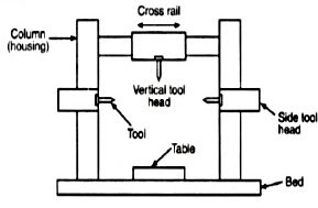
The main parts of the double Housing Planer machine is Bed and table, Housings, Cross rail, Tool heads, Driving and feed mechanism.

Bed and table: The bed is a long heavy base and table made of cast iron. Its top surface is flat and machine accurately. The flat top surface has slots in which the workpiece can be securely clamped. The workpiece needs rigid fixing so that it does not shift out of its position. The standard clamping devices used on planer machine are: Heavy duty vice, T-holders and clamps, angle plate, planer jack, step blocks and stop. The table movement may be actuated by a variable speed drive through a rack and pinion arrangement, or a hydraulic system.

Housings: The housings are the rigid and upright column like castings. These are located near the centre on each side of the base.

Cross rail: The cross rail is a horizontal member supported on the machined ways of the upright columns. Guide ways are provided on vertical face of each column and that enables up and vertical movement of the cross rail. The vertical movement of the cross rail allows to accommodate workpiece of different heights. Since the cross rail is supported at both the ends, this type of planer machine is rigid in construction.

Tool heads: Generally two tool heads are mounted in the horizontal cross rail and one on each of the vertical housing. Tool heads may be swiveled so that angular cuts can be made. Driving and feed mechanism: The tool heads may be fed either by hand or by power in crosswise or vertical direction. The motor drive is usually at one side of the planer near the centre and drive mechanism is located under the table. The size of the planer is specified by the maximum length of the stroke, and also by the size of the largest rectangular solid that can be machined on it.

SHAPER MACHINE


The shaper is a machine tool used primarily for:
  •        Producing a flat or plane surface which may be in a horizontal, a vertical or an angular plane.
  •        Making slots, grooves and keyways
  •        Producing contour of concave/convex or a combination of these.


Working Principle


The job is rigidly fixed on the machine table. The single point cutting tool held properly in the tool post is mounted on a reciprocating ram. The reciprocating motion of the ram is obtained by a quick return motion mechanism. As the ram reciprocates, the tool cuts the material during its forward stroke. During return, there is no cutting action and this stroke is called the idle stroke. The forward and return strokes constitute one operating cycle of the shaper.


Construction

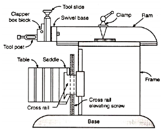
The main parts of the Shaper machine is Base, Body (Pillar, Frame, Column), Cross rail, Ram and tool head (Tool Post, Tool Slide, Clamper Box Block)

Base: The base is a heavy cast iron casting which is fixed to the shop floor. It supports the body frame and the entire load of the machine. The base absorbs and withstands vibrations and other forces which are likely to be induced during the shaping operations. Body (Pillar, Frame, Column): It is mounted on the base and houses the drive mechanism compressing the main drives, the gear box and the quick return mechanism for the ram movement. The top of the body provides guide ways for the ram and its front provides the guide ways for the cross rail.

Cross rail: The cross rail is mounted on the front of the body frame and can be moved up and down. The vertical movement of the cross rail permits jobs of different heights to be accommodated below the tool. Sliding along the cross rail is a saddle which carries the work table.

Ram and tool head: The ram is driven back and forth in its slides by the slotted link mechanism. The back and forth movement of ram is called stroke and it can be adjusted according to the length of the workpiece to be-machined.

PANTOGRAPH MECHANISM


        Pantograph is a linkage constituting of five link connected with pin joints to form revolute pairs. It is connected in a manner based on parallelograms so that the movement of one point, in tracing an image, produces identical movements by second point. In order to understand pantograph and its application we need to go through some basic terms associated with mechanisms.


link is defined as a rigid body having two or more pairing elements which connect it to other link is the frame of the machine and is called the fixed link.
Types of Links:
  • Rigid      : It undergoes no deformation; Example: crank, connecting rod.
  • Flexible  : Partial deformation; Example: springs, belts, ropes
  • Fluid       : Motion is transmitted by this link by deformation.     


kinematic pair:The two links or elements of a machine, when in contact with each other, are said to form a pair. If the relative motion between them is completely or successfully constrained (i.e. in a definite direction), the pair is known as kinematic pair.

(a) Lower pair: When the two elements of a pair have a surface contact when relative motion takes place and the surface of one element slides over the surface of the other, the
pair formed is known as lower pair.
(b) Higher pair: When the two elements of a pair have a line or point contact when relative motion takes place and the motion between the two elements is partly turning and partly
sliding, then the pair is known as higher pair. A pair of friction discs, toothed gearing, belt and rope drives, ball and roller etc

kinematic chain :When the kinematic pairs are coupled in such a way that the last link is joined to the first link to transmit definite motion, it is called as kinematic chain
Mechanism is a combination of various links which are capable of having relative motion with respect to one another. 
Machine is the combination of number of such mechanisms used to carry out a particular tasks.

Pantograph is used to reproduce to an enlarged or a reduced scale and as exactly as possible the path described by a given point.

   
It consists of a jointed parallelogram ABCD .It is made up of bars connected by turning pairs.The bars BA and BC are extended to O and E respectively, such that OA/OB =AD/BE
Thus,for all relative positions of the bars, the triangles OAD and OBE are similar and the points O, D and E are in one straight line. It may be proved that point E traces out the same path as described by point D. If a line drawing is traced by the first point D , an identical, enlarged, or miniaturized copy will be drawn by a pen fixed to the point  E. Other than that pantograph and its modifications can be used in the following areas.
  •    Transmission of electricity in trains
  •     Shaping and cutting the contour of a work piece of the desired profile.
  •     Magnification or dwindling of displacement for signal conditioning
  • .  Variable length testing gauges.
  •     Force multiplier.
  •     Elongation or compression of a work piece.
  •     Act as a lever-Isolator
  •     Precise positioning.


LATHE OPERATIONS


The engine lathe is an accurate and versatile machine on which many operations can be performed. These operations are:

1. Plain Turning and Step Turning
2. Facing
3. Parting
4. Drilling
5. Reaming
6. Boring
7. Knurling
8. Grooving
9. Threading
10. Forming
11. Chamfering
12. Filing and Polishing
13. Taper Turning

1. Plain Turning: Plain turning is the operation of removing excess amount of material from the surface of a cylindrical job.

2. Step Turning: Step turning produces various steps of different diameters.

3. Facing: The facing is a machining operation by which the end surface of the workpiece is made flat by removing metal from it.

4. Parting: The parting or cutting off is the operation of cutting away a desired length of the workpiece, i.e., dividing the workpiece in two or more parts.

5. Drilling: Drilling is the operation of producing a cylindrical hole in the workpiece.

6. Reaming: The holes that are produced by drilling are rarely straight and cylindrical in form. The reaming operation finishes and sizes the hole already drilled into the workpiece.

7. Boring: The boring operation is the process of enlarging a hole already produced by drilling.

8. Knurling: The knurling is a process of embossing (impressing) a diamond-shaped or straight-line pattern into the surface of workpiece. Knurling is essentially a roughening of the surface and is done to provide a better gripping surface.

9. Grooving: Grooving is the act of making grooves of reduced diameter in the workpiece.

10. Threading: Threading is the act of cutting of the required form of threads on the internal or external cylindrical surfaces.

11. Forming: The forming is an operation that produces a convex, concave or any irregular profile on the workpiece.

12. Chamfering: Chamfering removes the burrs and sharp edges, and thus makes the handling safe. Chamfering can be done by a form tool having angle equal to chamfer which is generally kept at 45°.
13. Filing and Polishing: The filing is the finishing operation that removes burrs, sharp corners and feed marks from the workpiece. After filing, the surface quality is the workpiece is improved by the polishing operation with the help of emery cloth of fine grades.
14. Taper Turning: The taper turning is an operation of producing a conical surface by gradual reduction in the diameter of a cylindrical workpiece.